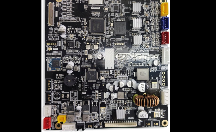
Pin out flashforge m5 main board Whether you’re upgrading components, troubleshooting issues, or exploring custom modifications, understanding the main board’s pinout on the Flashforge M5 can be a game-changer.
This guide provides a clear and accessible explanation of the Flashforge M5 main board pinout, tailored to both seasoned users and those new to 3D printer electronics. With this breakdown, you’ll be able to approach your 3D printing projects with increased confidence and efficiency. Let’s explore the essential connections and how they work together within the printer’s system.
The Role of the Pin out flashforge m5 main board
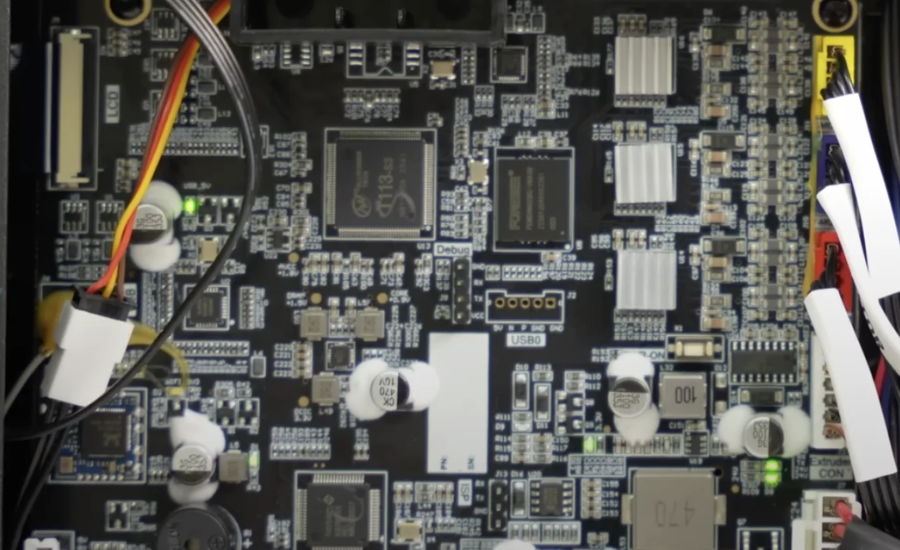
The main board, also known as the motherboard or control board, is the heart of your 3D printer. It manages and coordinates all of the printer’s essential functions, ensuring smooth communication between components like the motors, extruder, heated bed, sensors, and display.
For the Flashforge M5, the main board is fundamental to its overall performance. Gaining a solid understanding of its pin-out diagram is key for multiple tasks, whether you’re upgrading parts, installing custom firmware, or troubleshooting technical issues. A clear grasp of the board’s layout not only simplifies these processes but also helps ensure your printer continues to operate at its best.
The Importance of a Pin-out Diagram
A pin-out diagram provides a clear and detailed map of the pin layout on a circuit board. Each pin serves a specific function, whether it’s powering a motor, transmitting temperature data, or connecting to other components. By referencing the pin-out diagram, you can easily identify the role of each connection, ensuring proper placement of wires and components. This knowledge is essential when performing tasks like troubleshooting, upgrading parts, or implementing custom modifications to your 3D printer. Understanding the pin-out enhances your ability to maintain and optimize your printer’s performance.
Optimizing Performance with the Flashforge M5 Main Board
The Flashforge M5 main board is designed for high-performance, precise 3D printing. Understanding its pin-out can significantly enhance the printer’s operation and help with long-term maintenance.
By examining the pin-out, you gain clarity on how each component connects to the board, enabling smoother integration. This knowledge also allows for easy upgrades, like adding auto bed leveling or filament runout detection. Additionally, mastering the pin-out is essential for reliable maintenance, ensuring correct connections after repairs and minimizing errors or downtime. In essence, a solid understanding of the pin-out streamlines customizations, troubleshooting, and overall printer care, leading to a more efficient and adaptable 3D printing experience.
Key Connections on the Flashforge M5 Main Board
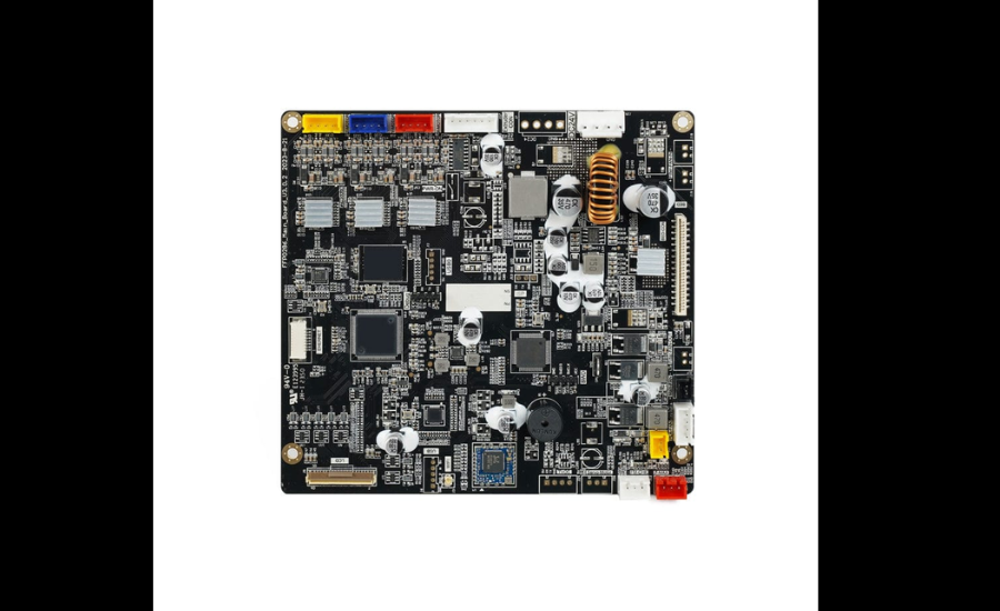
The Flashforge M5 main board contains several crucial connections that play a vital role in the printer’s smooth and efficient operation.
Power Input: These pins, usually located on the edge of the board, supply the 24V DC power needed for the main board and its components to function.
Stepper Motor Connectors: Separate pins are assigned to the X, Y, and Z motors for controlling the movement of the print head and build plate, while the E motor powers the extruder. It’s important to align the pins correctly to avoid any motion errors.
Endstop Pins: These connections link to limit switches or optical sensors, ensuring the printer recognizes when an axis reaches its limit (X_min, Y_min, Z_min).
Extruder and Heated Bed Connections: These pins control the heating of the extruder nozzle and the build plate, which are essential for maintaining the correct printing temperatures. Ensuring correct wiring prevents overheating or equipment damage.
Thermistor Connections: These pins track temperature readings from the extruder and heated bed. It’s crucial to ensure the thermistor is compatible with the type specified in your printer’s firmware.
Best Practices for Safe Printer Maintenance
Proper handling and preparation are key to maintaining the Flashforge M5’s performance during maintenance or upgrades.
Start by labeling the wires before disassembling any components. This simple step ensures that reassembly goes smoothly, preventing connection errors. Once you’ve made all your disconnections, take the time to carefully verify each connection before powering the printer back on. This extra check helps avoid damage or malfunctions from incorrect wiring.
For guidance or troubleshooting, make use of trusted resources such as the Flashforge manual or user forums, where you can find helpful tips specific to your model. When handling delicate components, always use the right tools, such as insulated tweezers, to minimize the risk of accidental damage. By following these precautions, you can ensure the safe handling and continued performance of your 3D printer.
Troubleshooting Common Printer Issues
If your printer isn’t powering on, the first thing to check is the power input pins. Ensure that all connections are secure. If the issue persists, use a multimeter to verify that power is reaching the board properly.
For incorrect motor movement, inspect the stepper motor connectors. If the motors are running in the wrong direction, try adjusting the connector orientation or modifying the settings in the firmware.
If you’re seeing inaccurate temperature readings, faulty thermistor wiring is often the culprit. Double-check the connections, and if necessary, replace the thermistor. Make sure the firmware matches the thermistor type installed.
If there’s no display output, check the display cable for loose or incorrect connections. Reseat the cable firmly, and if the issue remains, test the board with a compatible replacement screen.
By following these troubleshooting steps, you can quickly address common problems and keep your printer running smoothly.
Final Words
Understanding the pin-out of the Flashforge M5 main board is essential for optimizing performance, troubleshooting, and making upgrades. The main board controls critical components, such as stepper motors, the extruder, heated bed, and sensors. Familiarizing yourself with the pin-out diagram helps you correctly connect components, ensuring smooth printer operation and reducing the risk of errors. Whether you’re adding new features like auto bed leveling or addressing technical issues, knowing the pin-out simplifies the process. By following best practices for maintenance and using the right tools, you can keep your Flashforge M5 running at peak efficiency. A clear understanding of the pin-out diagram makes your 3D printing experience more reliable, adaptable, and efficient.
FAQs
1. What is a pin-out diagram for the Flashforge M5 main board?
A pin-out diagram is a detailed map of the connections on the main board of your Flashforge M5 3D printer. It helps you identify the specific functions of each pin, such as powering motors, transmitting temperature data, and connecting other components. Understanding this diagram ensures proper setup and maintenance of your printer.
2. Why is understanding the Flashforge M5 main board pin-out important?
Knowing the pin-out of the Flashforge M5 main board is crucial for troubleshooting, upgrading parts, or making custom modifications. It allows you to easily connect components correctly, minimize errors, and improve overall printer performance.
3. How can I use the pin-out diagram to troubleshoot my Flashforge M5 printer?
The pin-out diagram is useful for identifying issues with connections, such as loose wires or incorrectly connected components. For example, if your motor isn’t moving correctly, the diagram can help you check stepper motor connectors, ensuring the proper orientation and wiring.
4. Can I upgrade my Flashforge M5 with custom components using the pin-out diagram?
Yes, understanding the pin-out allows you to integrate new features, such as auto bed leveling or filament runout detection. It helps you identify where to connect additional components, ensuring smooth integration with the printer’s main board.
5. Where can I find the pin-out diagram for the Flashforge M5 main board?
The pin-out diagram is typically available in the printer’s manual or on the manufacturer’s website. Additionally, user forums and online communities can be valuable resources for finding diagrams and tips on using the pin-out effectively.
6. What are common issues I can solve by referring to the pin-out?
Some common issues include motor movement errors, inaccurate temperature readings, and display problems. By using the pin-out to verify connections, you can address these issues and ensure your printer functions smoothly.
For exclusive insights and updates, stay connected with Insight Rays.
